MSTP
Multiple Spanning Tree Protocol (MSTP) was first specified in IEEE 802.1s and is standardized in IEEE 802.1Q. MSTP enables multiple VLANs to be mapped to the same spanning-tree instance, reducing the number of spanning-tree instances needed to support a large number of VLANs.
. MSTP provides multiple forwarding paths for data traffic and enables load balancing. It improves the fault tolerance of the network because a failure in one instance, or forwarding path, does not affect other instances.
MSTP Instances: An STP process (which defines a root bridge, root port, designated port and blocking port for a group of switch) that can be share by multiple VLANs
We will show in our example
Now instead of having 9 different spanning-tree protocol instances running we have 2 instances running
.You will use MSTP is when you have a lot of VLANs. In large enterprise corporation.
You wont need MSTP if you have a local network with few VLANs.
All MST instances are numbered 0 through 4094. Instance
0 is a special instance for the region, known as the internal spanning
tree (IST).The IST is the only spanning-tree instance that sends and receives
BPDUs.
MSTP is compatible with other versions of spanning-tree.If for example, another neighbor switch is running rapid pvst+ or pvst+ , it can exchange message with that switch
MSTP Region: A group of switches sharing the following configuration attributes:
- region name
- revision number
- mapping table.
Three differences with VTP:
- Unlike VTP . when we made a switch that was propagated to the other switches, if we enter a change into one instance, that change need to be enter in each switch.
- Revision Number: With VTP we had a revision number that automatically incremented and say :"This is the latest version of information".In MSTP we have it as well , but it doesn't increment automatically
- Switches that exchange MSTP information , they don't exchange the entire mapping table
MST Configuration
1.-We will configure the VLAN in each Switch (please copy and paste in each one)
conf t
spanning-tree mst configuration
instance 1 vlan 110,450
instance 2 vlan 460
end
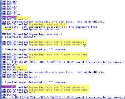
2.-Now we will apply the primary and secondary root on switch B and C
conf t
spanning-tree mst 1 ?
spanning-tree mst 1 root primary
spanning-tree mst 2 root secondary
end
3.-We will enable MSTP (Copy and paste in each switch)
spanning-tree mode ?
spanning-tree mode mst
end
4.- We will verify our configuration: show spanning-tree summary
5.- Another way to verify configuration: show spanning-tree mst configuration
6.- We will assigning a name Ccnp_Switch and a revision number 1 on each switch (copy and paste)
conf t
spanning-tree mst configuration
?
name Ccnp_Switch
revision 1
end
7.-We will issue the same previous command show spanning-tree mst configuration
8.- We will issue the command show spanning-tree vlan 110 on switch B
we see that our priority 28674 is not as low the default of the root bridge 24578
we will check that on switch C
9.- When we are exchanging information with other switches , we are not sending the whole mapping table , we are sending a hash Digest of the table
We will issue the command show spanning-tree mst configuration digest
With that command and checking the Name , Revision number and Digest we will know that the switches belongs to the same MSTP region as we explained before
We suggest that with MSTP , the switches must be interconnected with trunks, and don't prune any VLAN out of those trunks because it can lead to connectivity issues with MSTP
MSTP
 Reviewed by ohhhvictor
on
1:42:00 PM
Rating:
 Reviewed by ohhhvictor
on
1:42:00 PM
Rating:


No comments: