

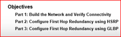
HSRP & GLBP
Hot Standby Routing Protocol (HSRP)

The first hop redundancy is the capability for one or more device to share a same IP address in order to give multidevice resiliency in the default gateway scenarios. Normally, it involves one device owning an IP address when the other devices stand by, ready to assume the control of an address if the main one fail.
There exists a class of redundancy protocols known as FHRP (First Hop Redundancy Protocols) that include VRRP (Virtual Router Redundancy Protocol), HSRP (Hot Standby Router Protocol), and GLBP (Gateway Load Balancing Protocol).
These protocols protect against a single point of failure for the default gateway and may also provide load balancing if multiple uplinks are available at first-hop routers.
HSRP is a Cisco-propietary First Hop Redundancy Protocol (FHRP) for establishing a fault-tolerant default gateway and is the most popular of the Cisco shops used to accomplish it, however outside of a Cisco World the VRRP is a standard one (IEEE).
Unlike HSRP or GLBP, VRPP is an open standard.In VRRP, the active router is referred to as the Master Virtual Router, that is responsible of answering ARP request
A GLBP group only has a maximum of four AVFs (means four virtual MAC addresses).
If there are more than 4 gateways in a GLBP group then the rest will become Standby Virtual Forwarder (SVF) which will take the place of a AVF in case of failure.
The Active Virtual Gateway (AVG) is responsible for answering the ARP
Request for the virtual IP address.
Load sharing is achieved by the AVG replying to the ARP requests with different virtual MAC addresses.

Let's check this graphic so you will understand way better..


I know that a lot of this terms could sound confusing..But when you see the application on the next exercise , you would understand much better. and hopefully all these concepts will be crystal clear to you!
We are going to make a lab in packet tracer, instead of real equipment so you can graphically see what we are doing, and you understand the relationship between the different devices.
Here is the original lab (copy & paste): goo.gl/xz0hMr

We are not going through every single step because some of them are very obvious and basic, and we want you to focus on this lab
This is the original topology in the lab

This is our Packet tracert configuration

We are going to follow the commands.
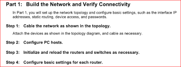
Step 1 is done
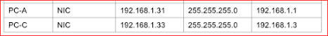
Step 2:Configure the PC's


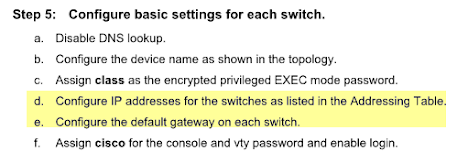
We will continue with these step:5(D&E)
We will do Router 1


Load sharing is achieved by the AVG replying to the ARP requests with different virtual MAC addresses.

Let's check this graphic so you will understand way better..

Concepts to handle HSRP
- Router 1 and 2 are actually 2 multilayer switches but in this case we will refer them as Routers since the terminology refers as "Active routers" and "Standby routers"
- The default gateway of the PC is 10.1.1.100, the ip address of the virtual router
- If the link of R1 goes down , maybe it wouldn't be able to reach beyond his local subnet, that's when HRSP , the redundancy protocol comes over
- In the middle there is a phantom router or Virtual Router that the PC is logically using and it has the ip address of the default gateway of the PC
- In something goes bad with the link of R1, R2 goes immediately from Standby state to Active state
- R1 and R2 exchange Hello Message every 3 seconds.They elect the Active Router and let the Standby Router knows the Active Router is still available
- Holdtime, a time after which the standby Router becomes the Active Router- the holdtime must be at least 3X the hello interval
- Interface Tracking monitor the status of an interface and can decrements a priority value if that interface goes down.Basically what it does is that If an interface goes down HSRP can change the priority.
- Active Router Election : The router with the highest priority is elected as the Active Router - And the default priority is 100
- The default decrement value for HSRP standby tracking is 10. There is no need to explicitly state the value if the desired value is the default value.1
- Preempt Option : Allows a Router that was previously an Active Router to reclaim it's role as the Active Router , if it goes down and comes back up, or its priority get increased to the highest value
- Enhanced Object Tracking : Allows a priority value to be decremented based on a variety of network conditions .-For example Internet went down, a link to the server went down, or a route not longer appears in a router 's IP routing table,etc
I know that a lot of this terms could sound confusing..But when you see the application on the next exercise , you would understand much better. and hopefully all these concepts will be crystal clear to you!
HSRP Lab
We are going to make a lab in packet tracer, instead of real equipment so you can graphically see what we are doing, and you understand the relationship between the different devices.
Here is the original lab (copy & paste): goo.gl/xz0hMr
This is the original topology in the lab

This is our Packet tracert configuration


Step 1 is done
Step 2:Configure the PC's


We will continue with these step:5(D&E)

Routers and Switches configuration
We will do Router 1

R2

R3

S1

S3

Check that the default gateway of the pc's are the ip address of the switches


 A)
A)


B) loopback 1 is a simulation to an exit to the internet

 We got similar results in PC-C

We found this question in Step 1:
 We see that it took the path of Gi0/0 of R1 and loopback 1 in R2.The next question is similar so we wont answer it.
The Step 2 ask to start a ping session from PCa to the loopback and break the session

The eventual result is that the ping ( and connection) fails after we disconnect the cable to R1.Similar results on PC-C.We will eventually reconnect everything..

R1:


We will verify HSRP with the "show standby" command on R1


We could see the active role , the real and virtual IP address.Similar results are in R3 with the difference of priority 100 and standby state
We will change the default gateway on PC-A , PC-C, S1 and S3 and we will use the virtual IP 192.168.1.254


We will now see the results of pinging the loopback of R2 from PC-A

It 's successful.


 The traffic was interrupted , and the standby router of R3 start working now and is taking over.
We will issue the "standby brief "command on R1 and R3
R1
 R3
R3

We will reconnect the cable and we will disable the HSRP configuration on R1 and R3

By default HSRP doesn't do load balancing.There are different ways to do load balancing with GLBP.In this occasion we will use round robin method.
Packet tracert doesn't recognize commands of GLBP so we will continue with GNS3 so you can graphically see what we are doing, but at the same time , GNS3 doesn't have configure Cisco switches, so we have some limitations in this lab.
We will do the step 1:We will configure GLBP on R1 and R3
R1

R3

Step 2 : We will issue the command "Show glbp brief"
R1:

R3

We see the different priority in the two routers but in GLBP we have the the same virtual ip address and two more mac address :one for each router .
Step 3 would be to generate traffic but GNS3 can not emulate a Cisco Switch , but we can expect a similar results like hsrp with load balancing.
On the reflection
We will answer some questions:
The need of redundancy; it today's business there is a need of redundancy because a lot of business run 24/7 and we need to know how to properly design, implement, monitor and test in case of any disaster that may occur as well as covering briefly other redundancy options. Today’s businesses require reliable network connectivity and access to corporate resources.
When active router goes down standby router acts as a active router role and another router in standby Group acts as a Standby router
HSRP does not support loadbalance.
In GLBP you can loadbalance both link. It seems more sufficient to use GLBP since you get redundancy and better throughput and performance.
I hope that you enjoy and understand this long lab.If you have any question, please feel free to ask.
If you like it please share.


R1

R3

R2

B) loopback 1 is a simulation to an exit to the internet


Part 2: Configure First Host Redundancy using HSRP

We found this question in Step 1:

The Step 2 ask to start a ping session from PCa to the loopback and break the session

The eventual result is that the ping ( and connection) fails after we disconnect the cable to R1.Similar results on PC-C.We will eventually reconnect everything..
Step 3: Configure HSRP in R1 and R3
R1:

R3


R3

We could see that R3 has a lower priority (100 by default), the virtual Mac address is the same and the active router is R1 (Check the IP address )
We will use the command "show standby brief" to verify the HSRP status of R1 and R3
R1

R2

We could see the active role , the real and virtual IP address.Similar results are in R3 with the difference of priority 100 and standby state
We will change the default gateway on PC-A , PC-C, S1 and S3 and we will use the virtual IP 192.168.1.254

We will now see the results of pinging the loopback of R2 from PC-A

It 's successful.


We will issue the "standby brief "command on R1 and R3
R1


We will reconnect the cable and we will disable the HSRP configuration on R1 and R3

PART 3 : Configure HSRP using GLBP
By default HSRP doesn't do load balancing.There are different ways to do load balancing with GLBP.In this occasion we will use round robin method.
Packet tracert doesn't recognize commands of GLBP so we will continue with GNS3 so you can graphically see what we are doing, but at the same time , GNS3 doesn't have configure Cisco switches, so we have some limitations in this lab.
We will do the step 1:We will configure GLBP on R1 and R3
R1

R3

Step 2 : We will issue the command "Show glbp brief"
R1:

R3

We see the different priority in the two routers but in GLBP we have the the same virtual ip address and two more mac address :one for each router .
Step 3 would be to generate traffic but GNS3 can not emulate a Cisco Switch , but we can expect a similar results like hsrp with load balancing.
On the reflection
We will answer some questions:
The need of redundancy; it today's business there is a need of redundancy because a lot of business run 24/7 and we need to know how to properly design, implement, monitor and test in case of any disaster that may occur as well as covering briefly other redundancy options. Today’s businesses require reliable network connectivity and access to corporate resources.
Which one to choose GLBP or HSRP?:
When using HSRP one router is active and another router is standby mode When active router goes down standby router acts as a active router role and another router in standby Group acts as a Standby router
HSRP does not support loadbalance.
In GLBP you can loadbalance both link. It seems more sufficient to use GLBP since you get redundancy and better throughput and performance.
I hope that you enjoy and understand this long lab.If you have any question, please feel free to ask.
If you like it please share.
HSRP & GLBP
 Reviewed by ohhhvictor
on
5:48:00 PM
Rating:
Reviewed by ohhhvictor
on
5:48:00 PM
Rating:
Reviewed by ohhhvictor
on
5:48:00 PM
Rating:


No comments: